-
Continuous Drying Systems (CDS)
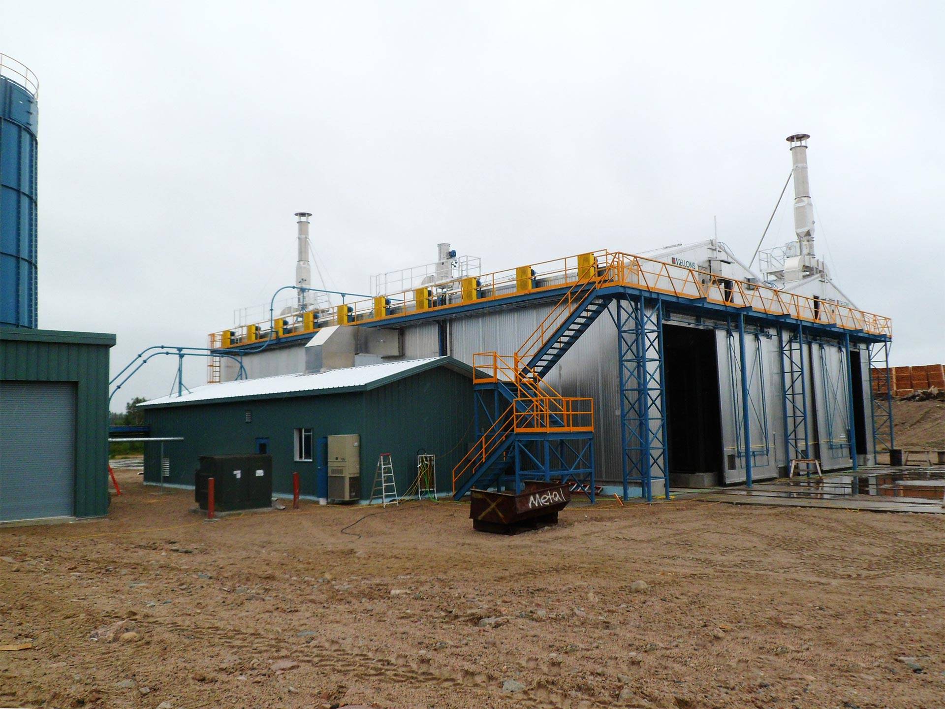
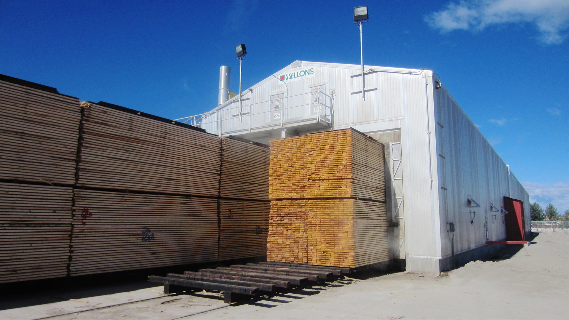
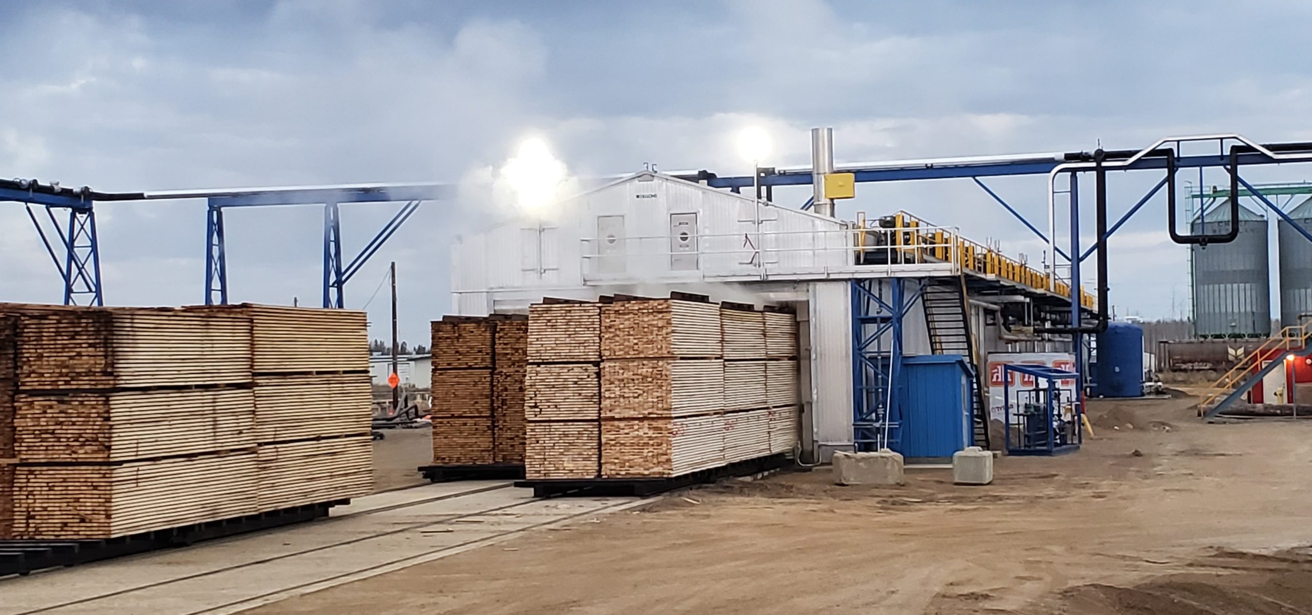
Continuous Drying Systems have rapidly gained popularity as the benchmark lumber drying technology due to their increased production capability, energy efficiency, and drying quality. The Wellons Continuous Counter Flow (CCF) Drying System is a counter flow, double track design, incorporating preheating, drying, cooling, equalizing and conditioning phases all in one extended chamber.
The Wellons continuous drying system is custom designed to meet your unique drying and production requirements.
Continuous Drying Systems
Operating Principles
Continuous Drying Systems
Technology Benefits
Continuous Drying Systems
Structure & Cladding
Continuous Drying Systems
Heat System
Continuous Drying Systems
Single Point Exhaust
Continuous Drying Systems
Fan System
Continuous Drying Systems
Features & Options
Continuous Drying Systems
Retrofits of Existing Batch Kilns
Continuous Drying Systems
Operating Principles
The CDS is a double track kiln with three separate sections along the length of the kiln isolated by baffles. The main drying section (MD) is flanked by two energy recovery sections (ER). The lumber is automatically advanced by a set of hydraulic pushers based on an established travel rate with adjustments based on moisture content. The packages are loaded and unloaded at both ends of the kiln.
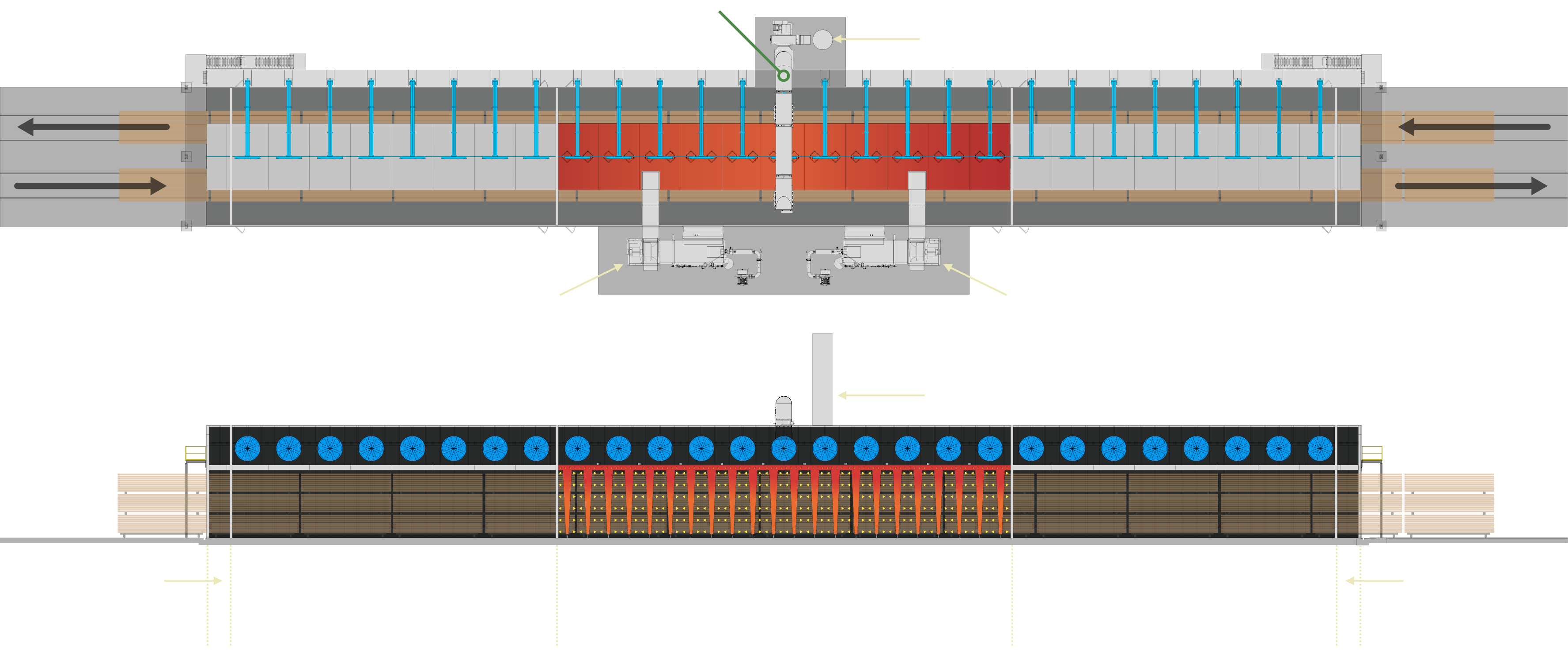
Direct-Fired Counter Flow System
The Main Drying (MD) Section incorporates heat input (see Heat Media Options below) and air circulation. The majority of the lumber drying occurs in the MD section.
The Energy Recovery (ER) Sections are at either end of the main drying section and have air circulation only. The ER sections heat the load entering the kiln and condition the load leaving the kiln.
ER Sections enhance the following:
The efficiency of the CDS by capturing the heat energy from the exiting load and preheating the incoming load before it enters the drying section (MD)
The drying quality by allowing the exiting load to condition and equalize before leaving the CDS.
Continuous Drying Systems
Technology Benefits
Reduced energy drying costs (per board foot) due to the counter-flow heat exchange which occurs in the Energy Recovery (ER) sections of the CDS
Improved grade recovery due to the conditioning / equalizing which occurs in the ER sections
Lower standard deviation on target MC due to the uniformity of the continuous counter-flow drying process
System utilization is optimal as the CDS is always 100% full of lumber, regardless of what the lumber/package lengths are; i.e. no gaps or air bypass.
Continuous Drying Systems
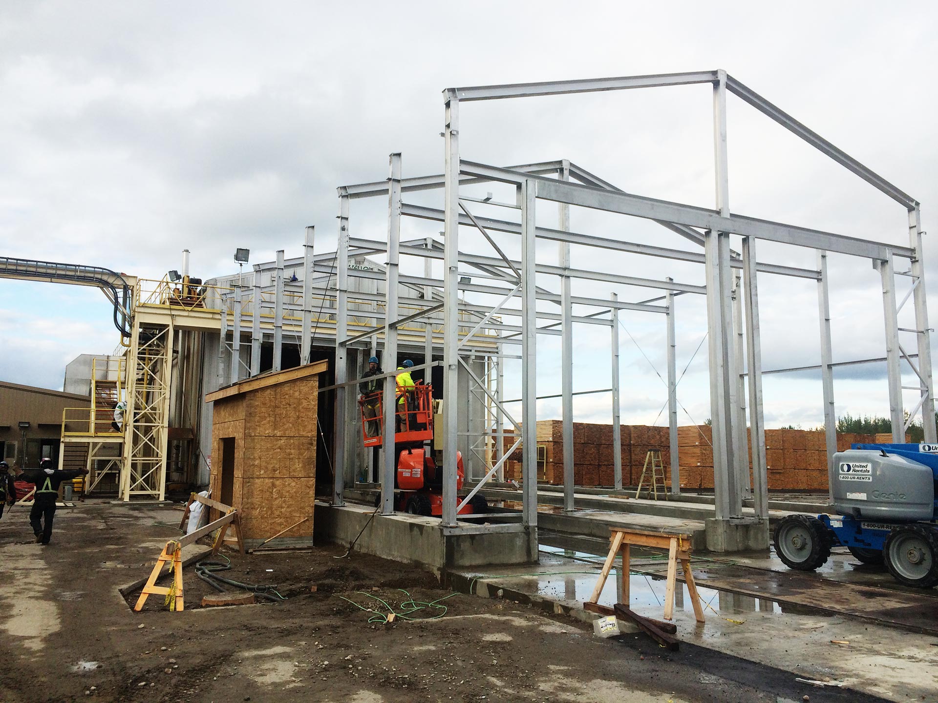
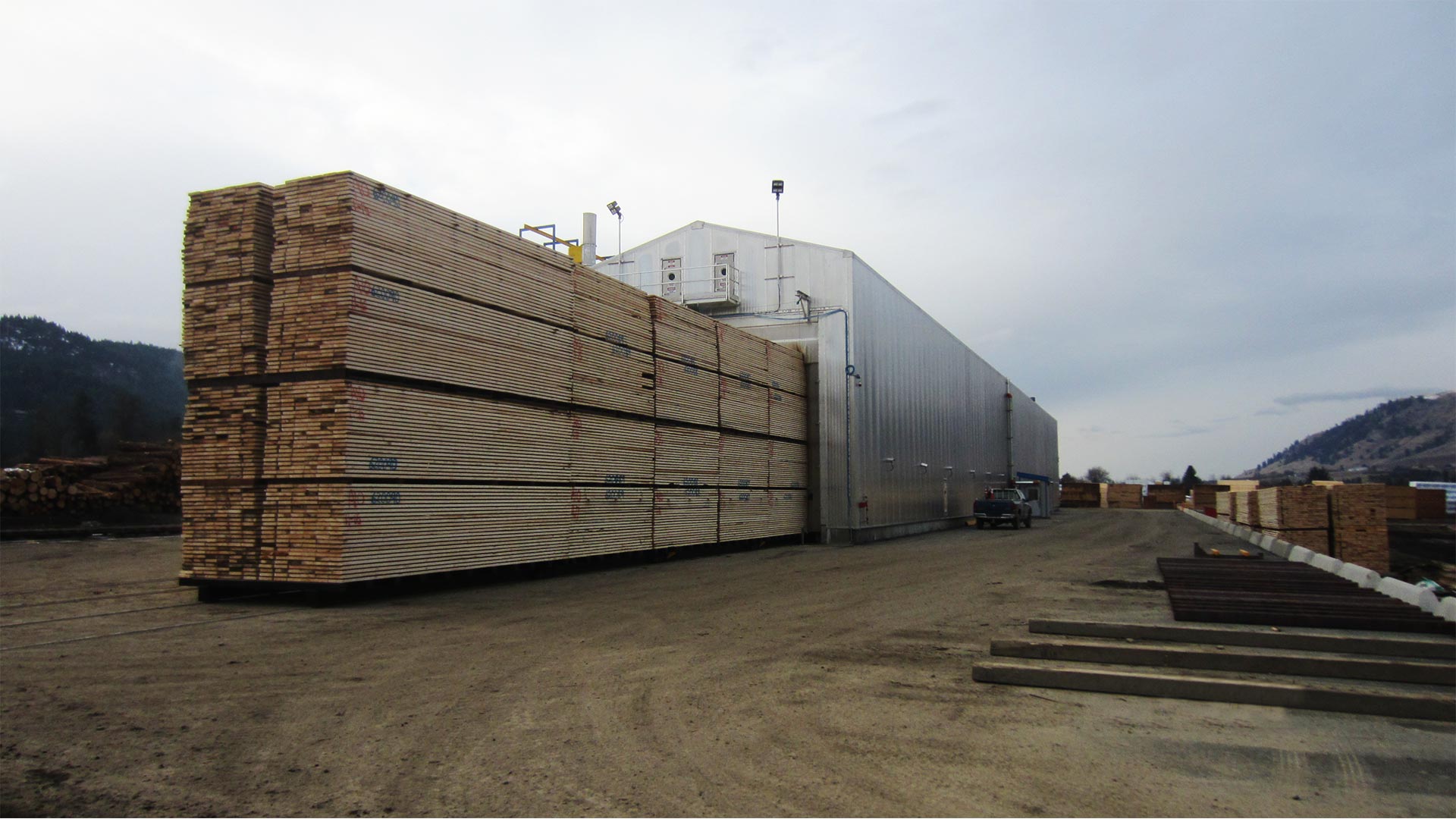
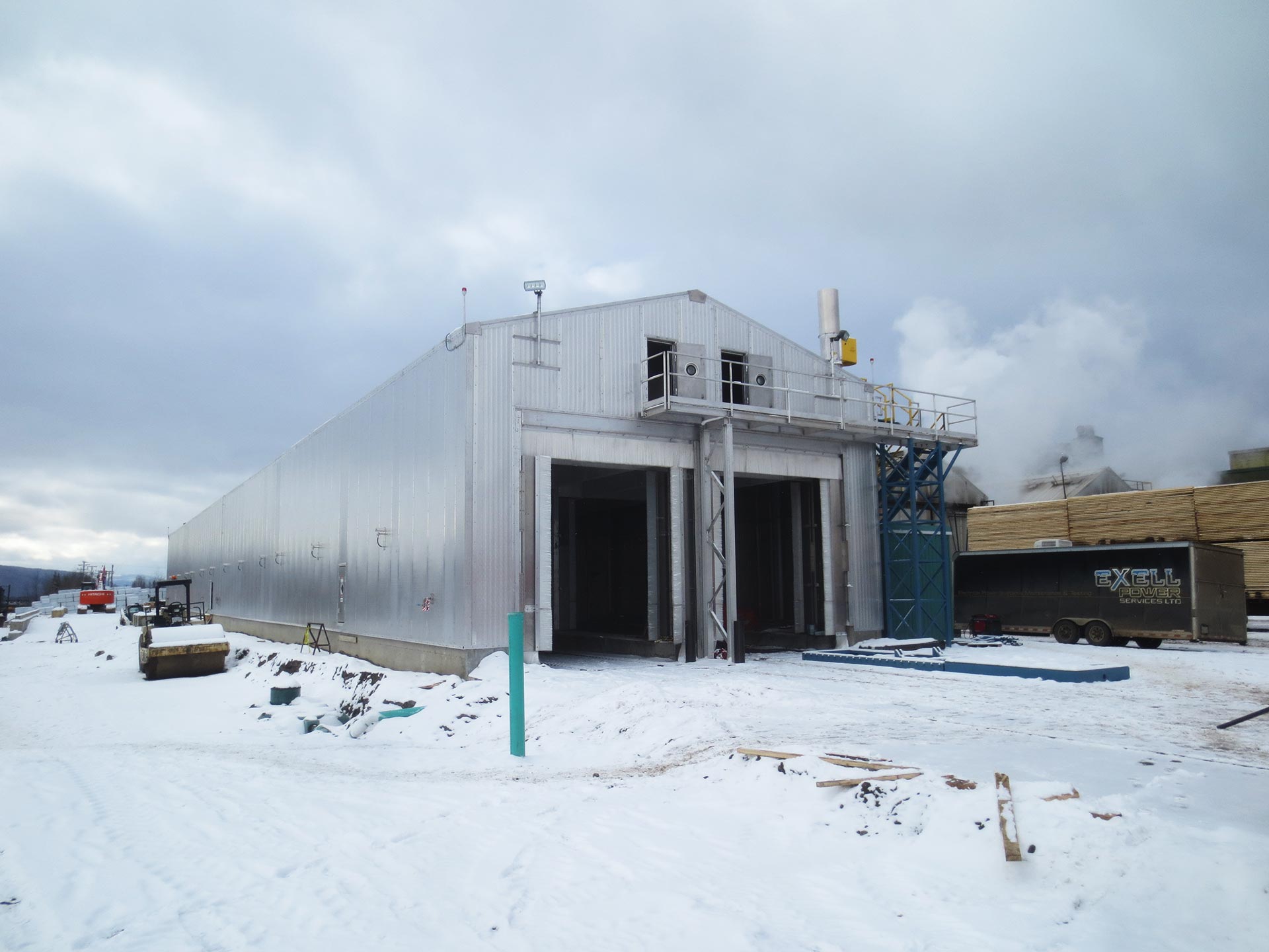
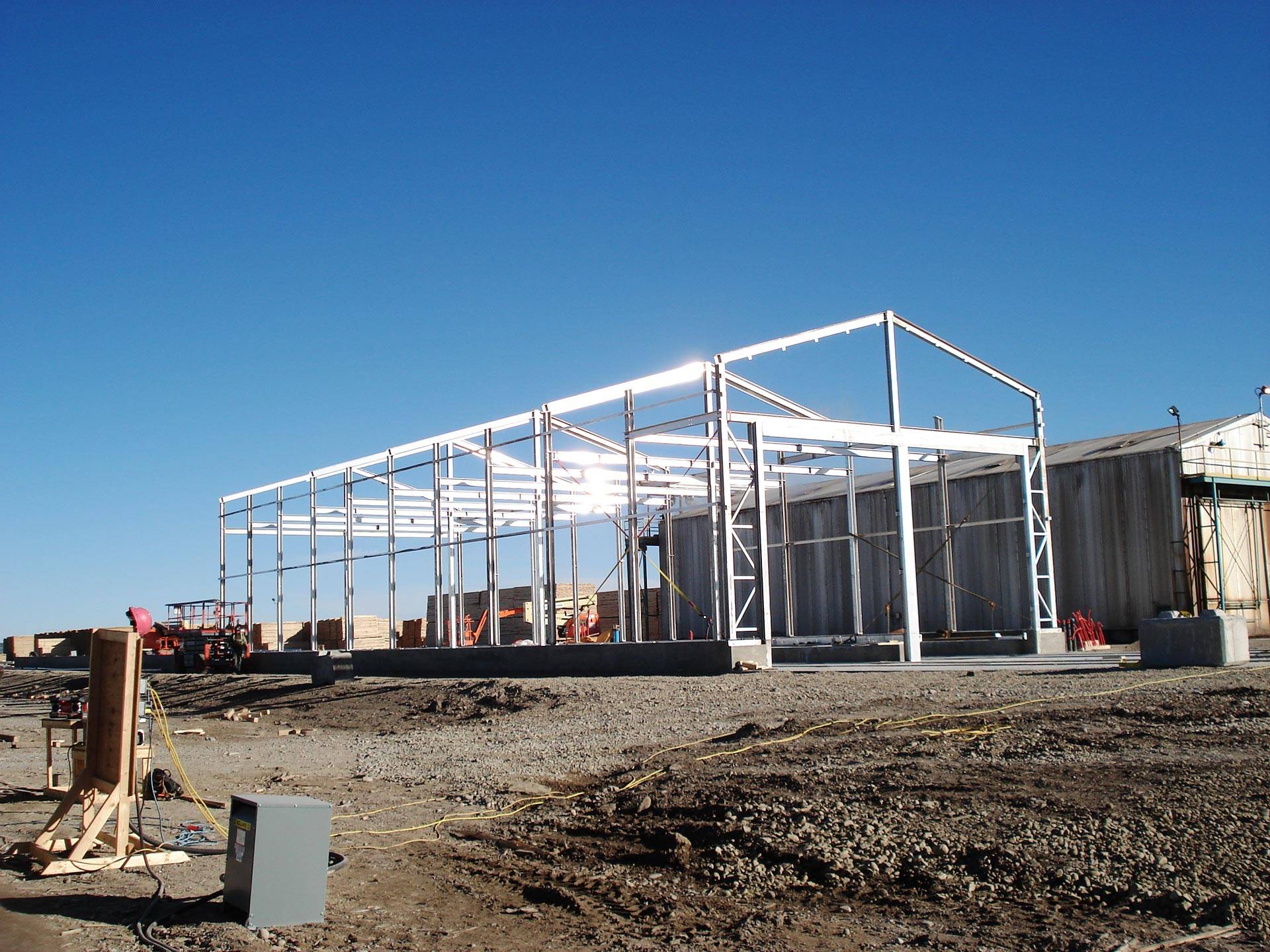
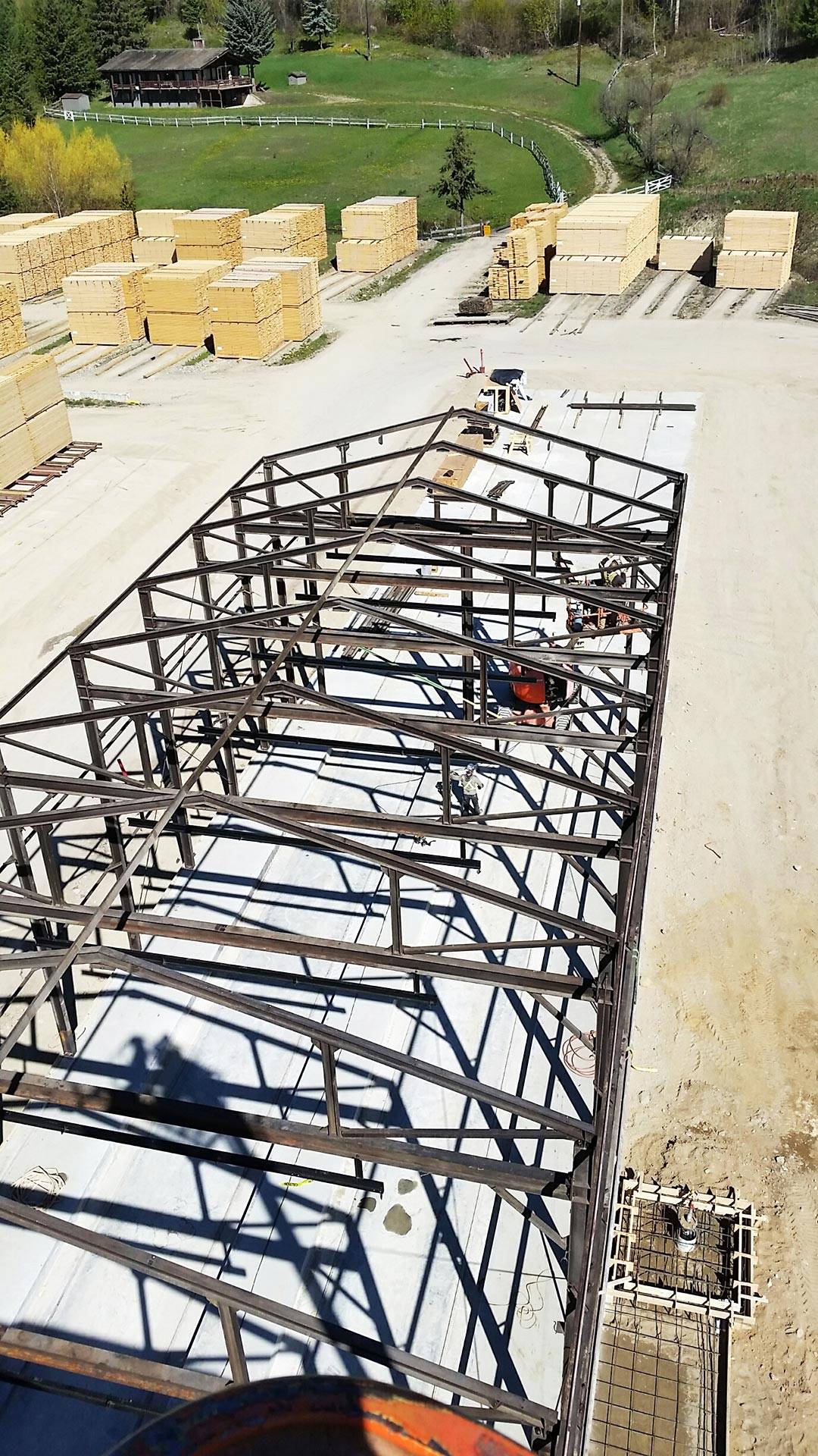
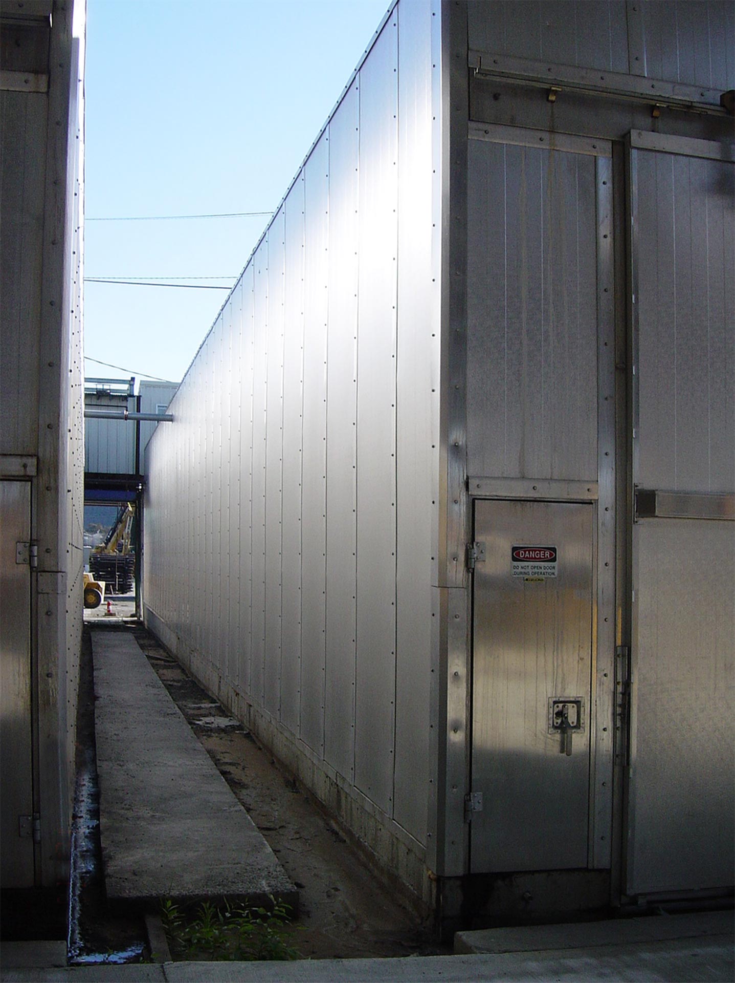
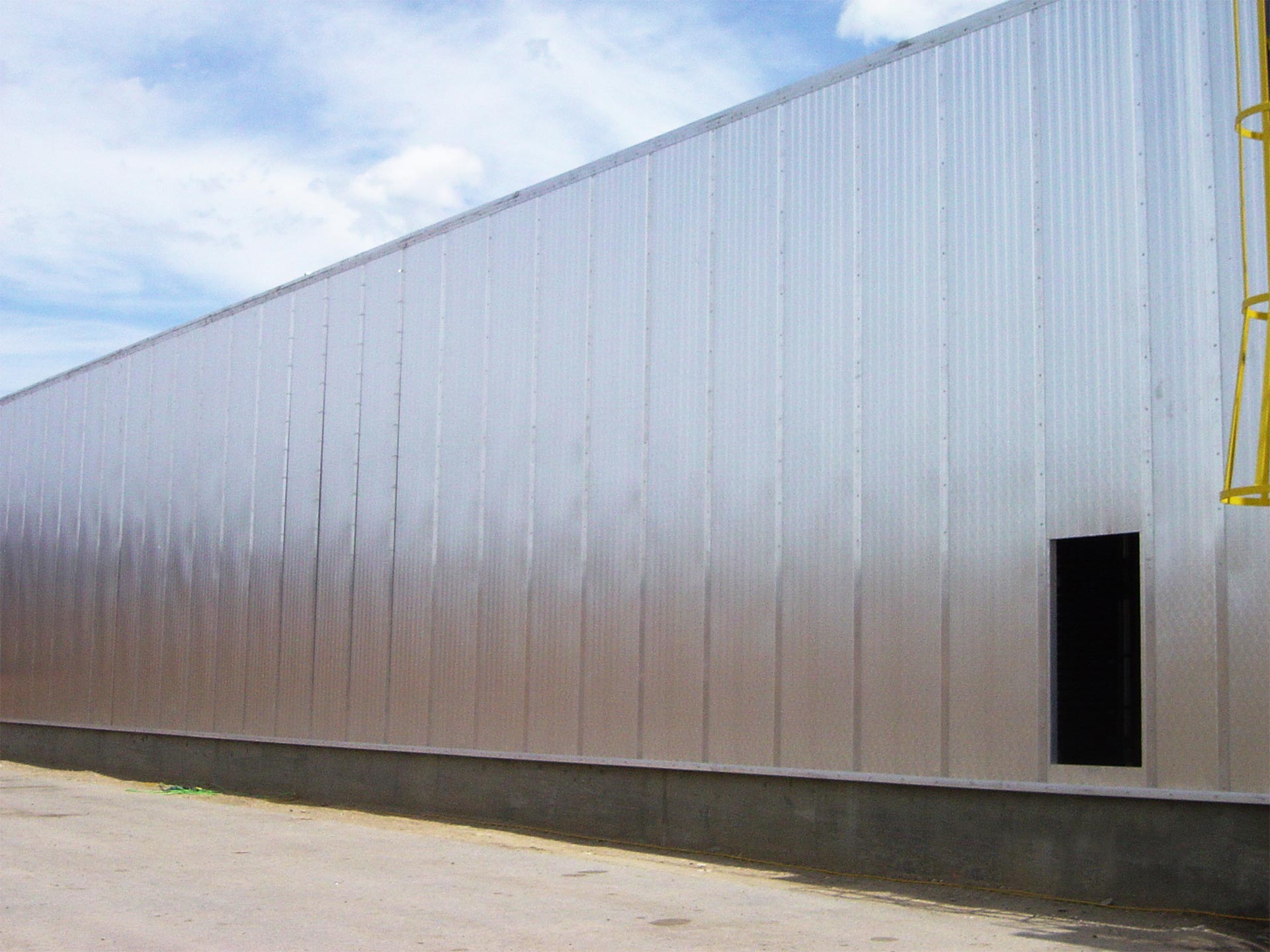
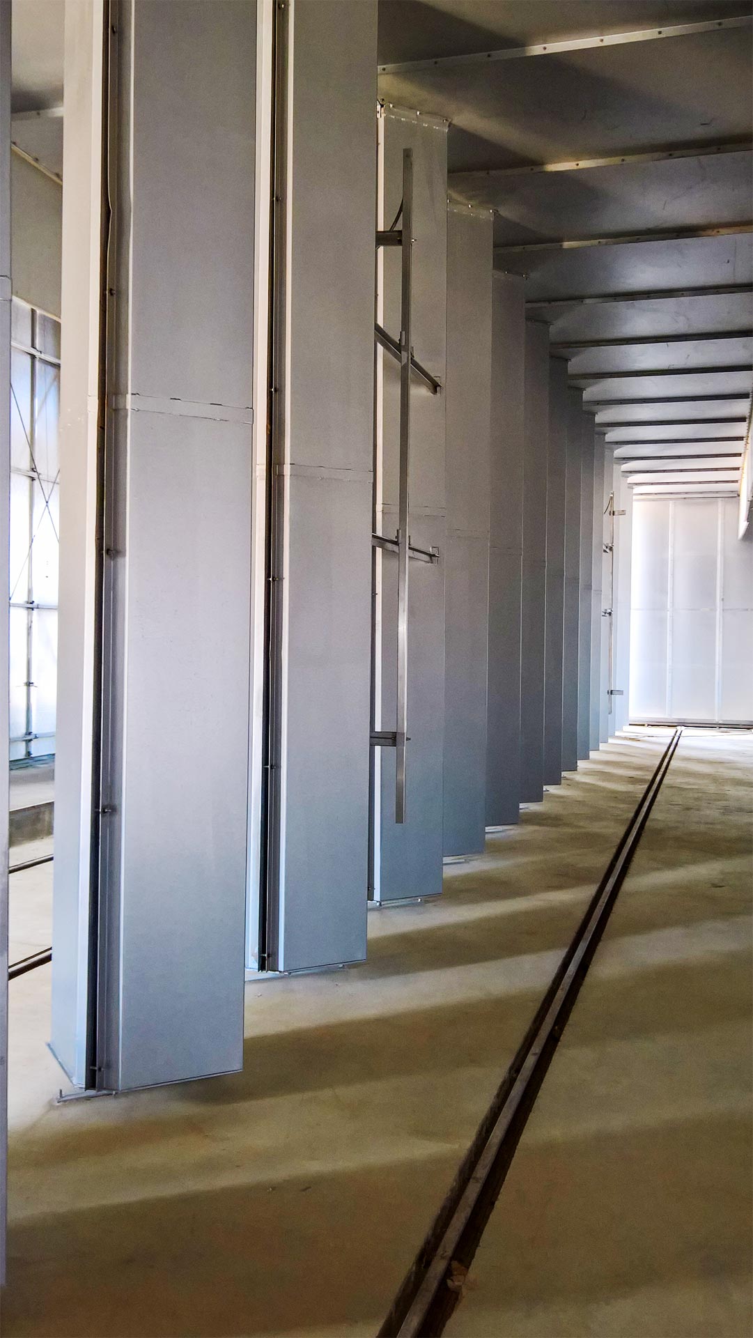
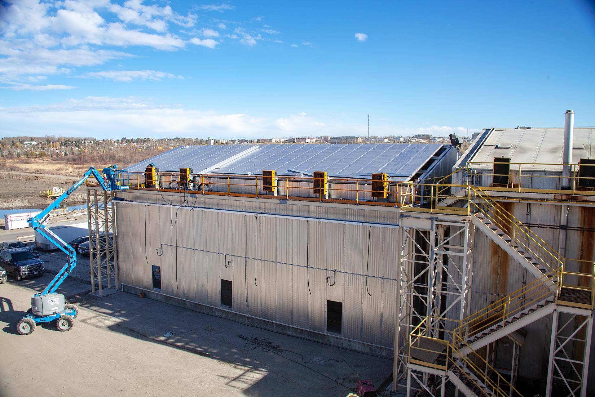
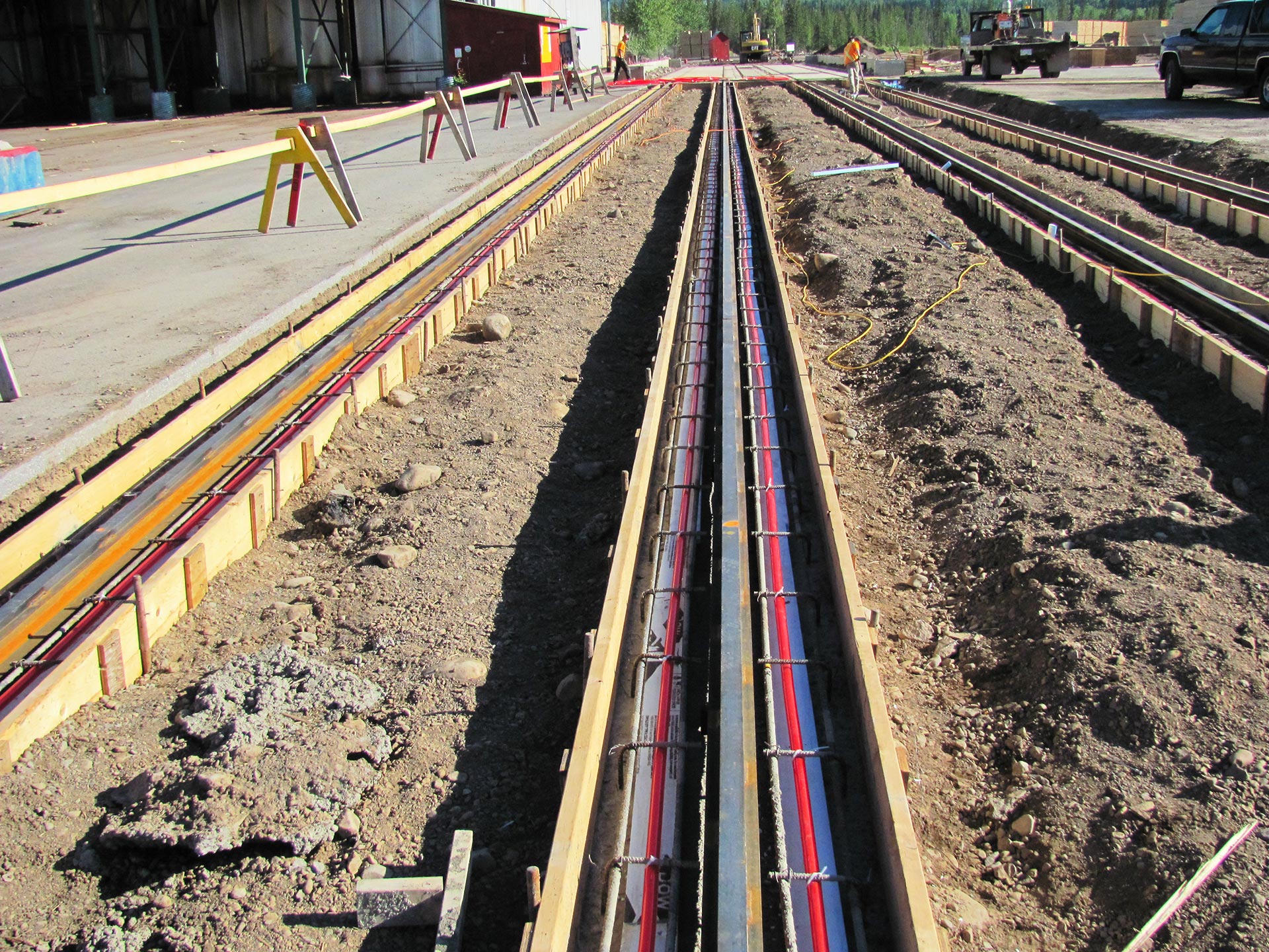
Structure & Cladding
The kiln structure can be made from mild steel, aluminum or stainless steel (or a hybrid of the three) depending on the corrosive environment in the kiln and the desired life expectancy.
The interior and exterior surfaces of the wall, roof, and door panels are clad with high grade aluminum. Rigid board insulation with a high R value provides excellent thermal efficiency and high temperature performance.
Continuous Drying Systems
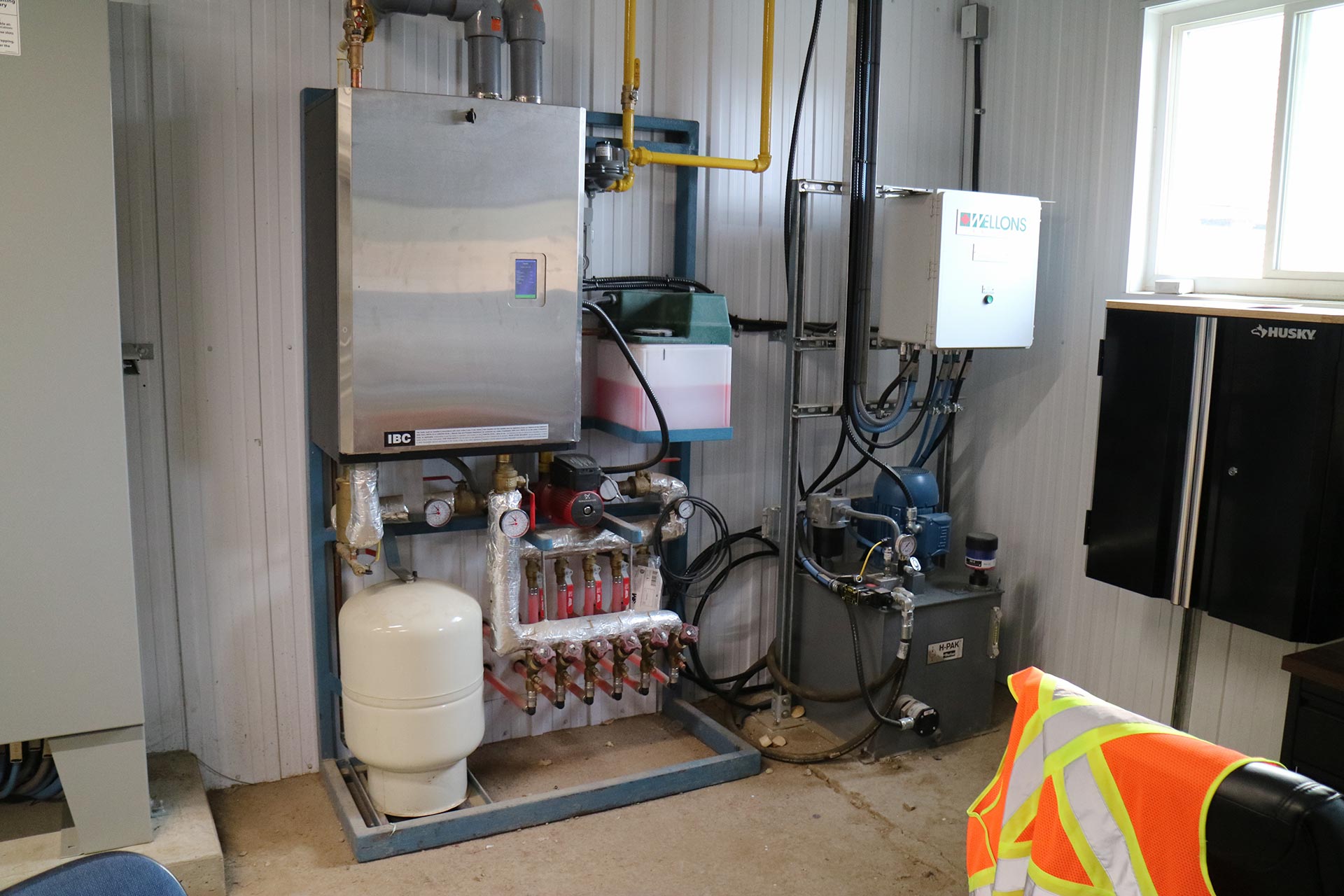
Heat Media Options
- Indirect Heat Systems
Wellons Indirect Heating Systems include Steam, Thermal Oil, or Hot Water as the heat medium. The heating systems are divided into stations and zones within the kiln for precise lumber drying.
Steam Heat
The steam heating system receives steam into a supply header from a boiler system which branches into several controlled zones. Each zone is controlled by either a pneumatic or electric valve which controls the flow rate of steam to each coil bank. Each coil bank is individually trapped and drains to a condensate return system. Humidity is vented through automatically controlled vents. Wellons designs systems for high pressure or low pressure steam depending on the drying application.
Thermal Oil & Hot Water
Thermal oil or hot water is pumped from the respective supply via a Primary Loop which sends and receives the fluid to and from the system. The fluid is directed to a header at each individual chamber where 2-way control valves adjust the fluid rate to the coil banks. Each valve and coil bank make up a zone within the system. The coil banks are fabricated of continually-welded, serpentine coils (fin pipe). The fluid is returned to the pumping system to reheat the fluid and return it back to the system.
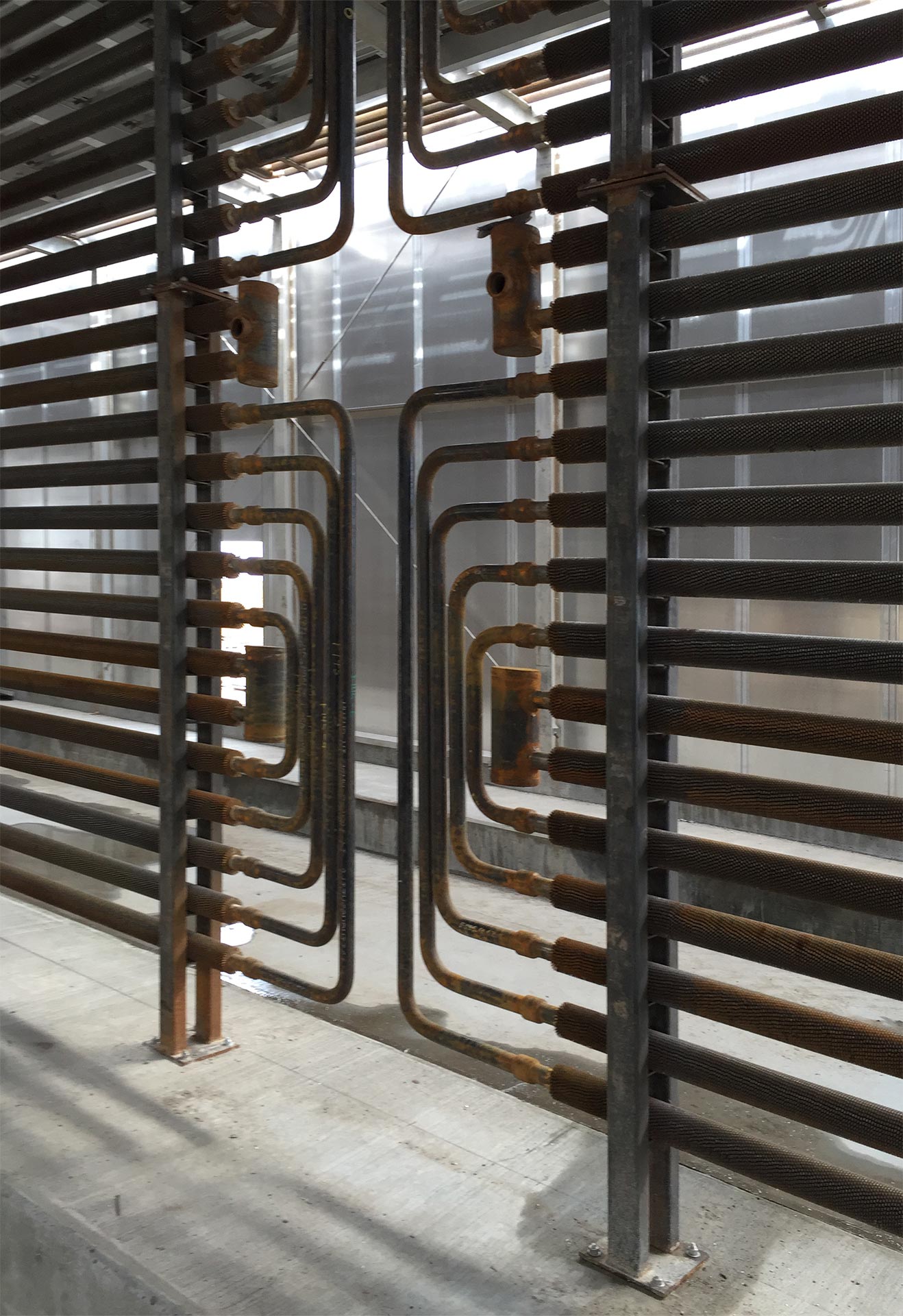
Heating Coils
Wellons manufactures their own standard and high heat release coil banks. Many options of fin pipe are available based on heating requirements of the customer, including:
33 wraps per foot, Sch 40 2” pipe
48 wraps per foot, Sch 40 2” pipe
60 wraps per foot, Sch 40 2” pipe
All Aluminum/Stainless Steel fin pipe
- Direct-Fired Heat Systems
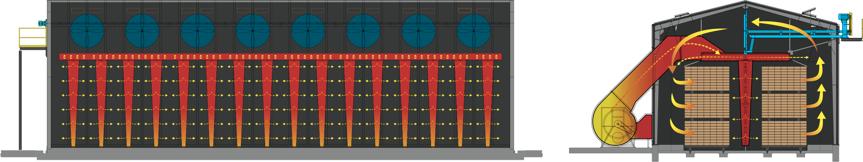
Direct-Fired systems circulate hot gases throughout the MD section utilizing down-comers and a supply and return ducting system. Direct-Fired heating systems receive hot gases from a supply burner. The gases are directed through overhead supply ductwork into the MD section and distributed throughout using down-comers along its length. The gases are directed and controlled in the down-comers utilizing a series of adjustable dampers. Excess gases are directed through return ducting into the recirculating fan. Heat supply options include Direct-Fired Biomass, Natural Gas, or Propane.
Continuous Drying Systems
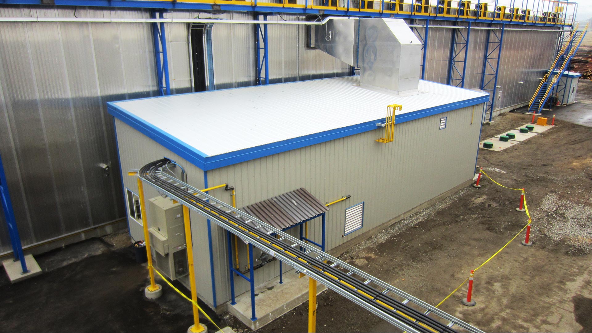
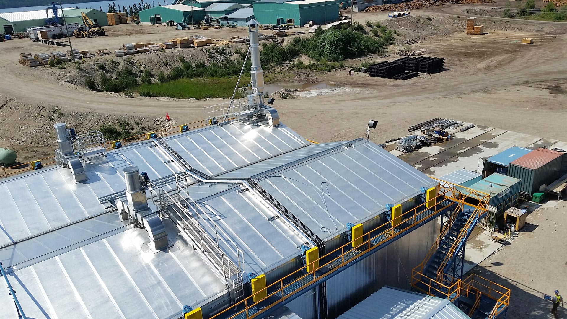
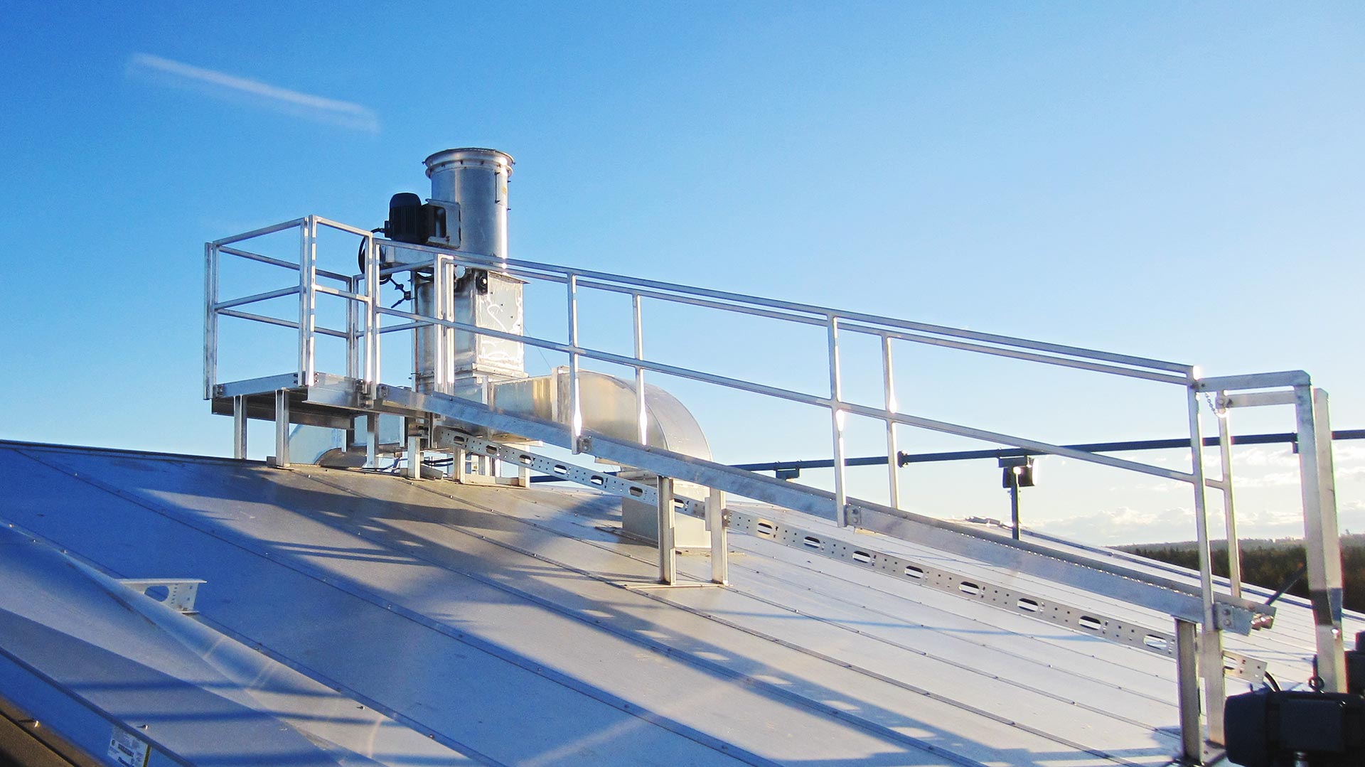
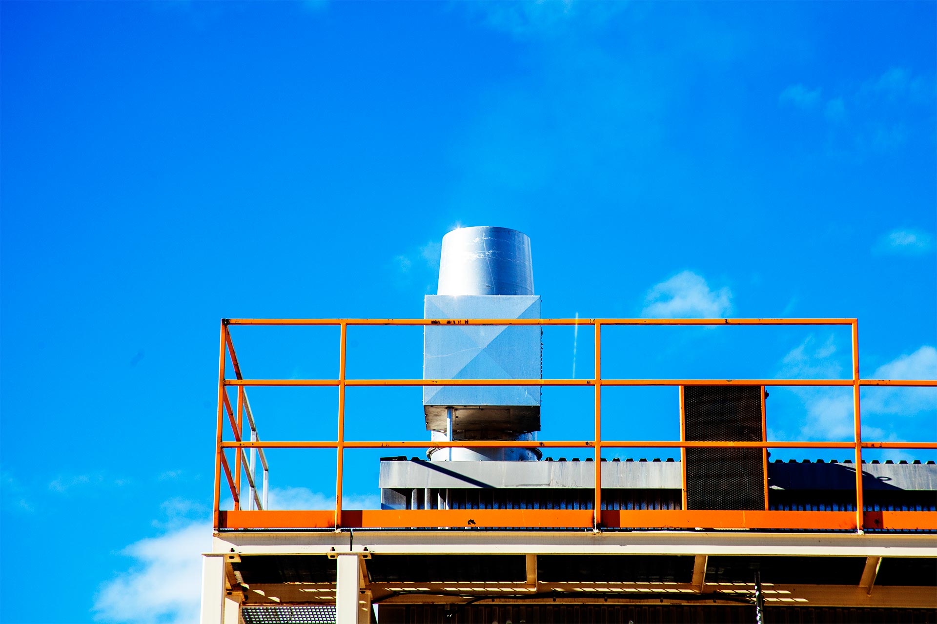
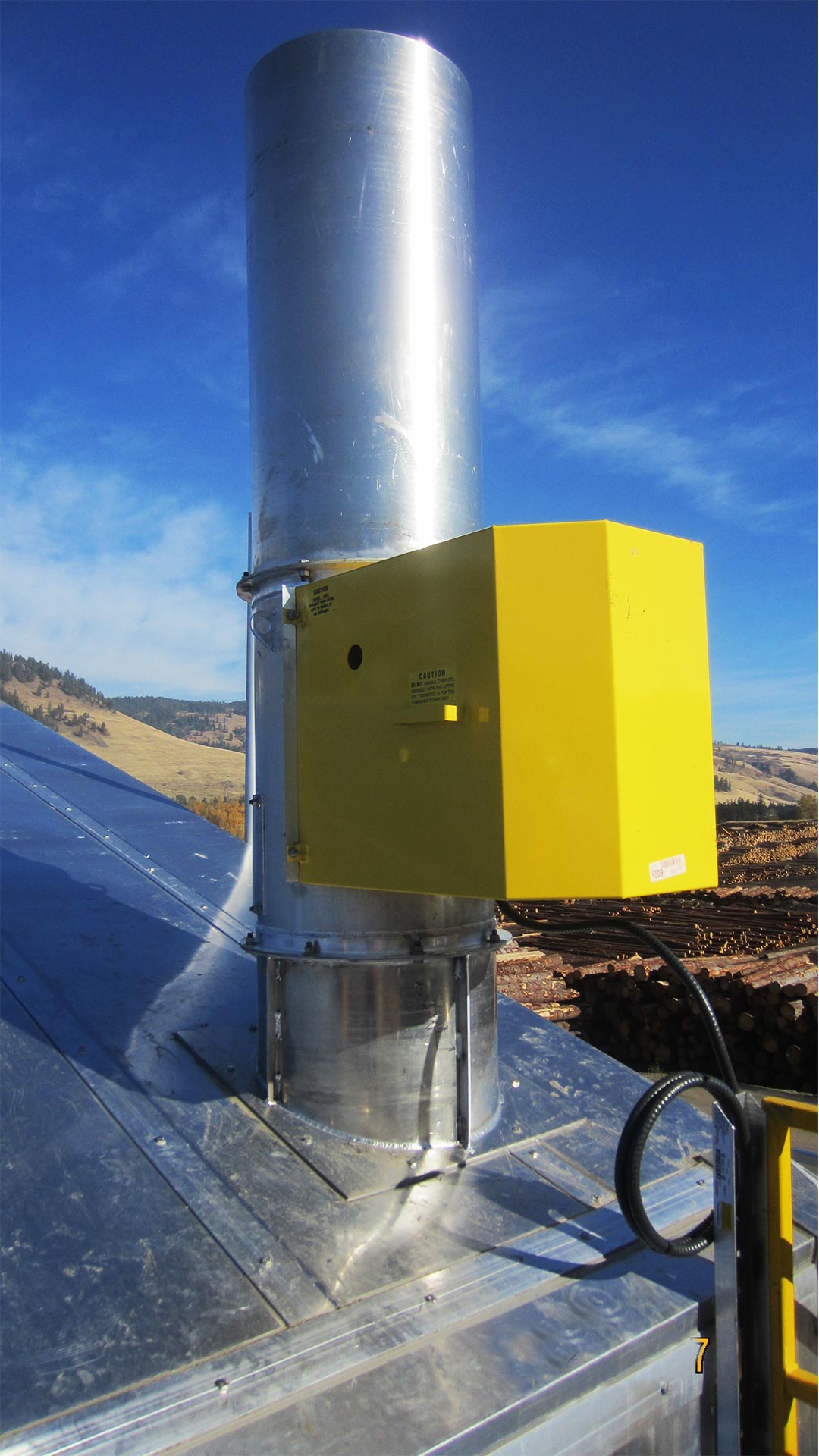
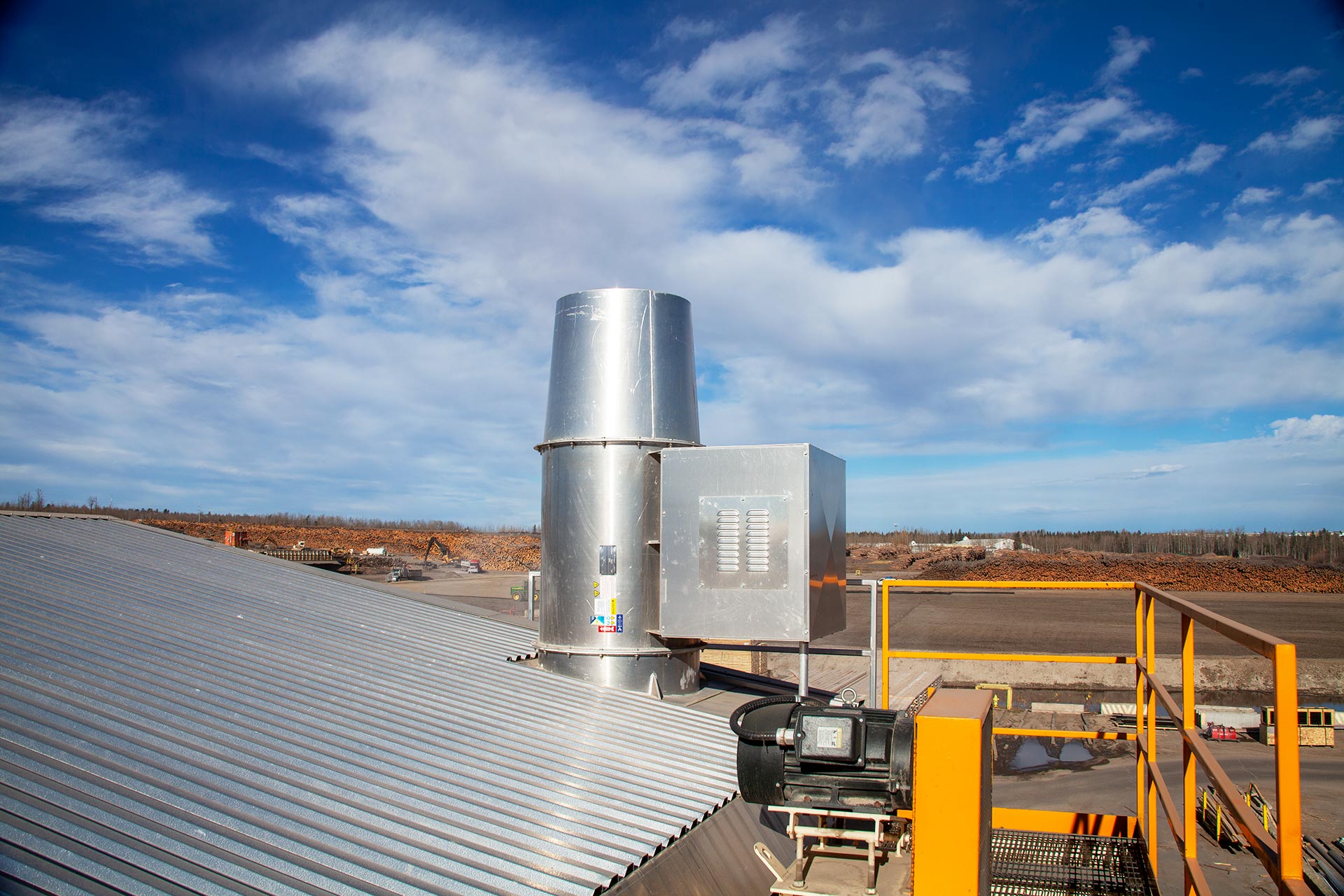
Single Point Exhaust & Supply Vent
We can also install a Continuous Emissions Monitoring system (CEMS) to facilitate reporting requirements.
Continuous Drying Systems
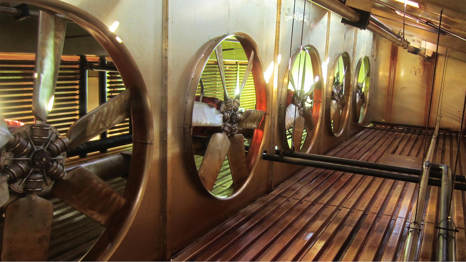
Fan System
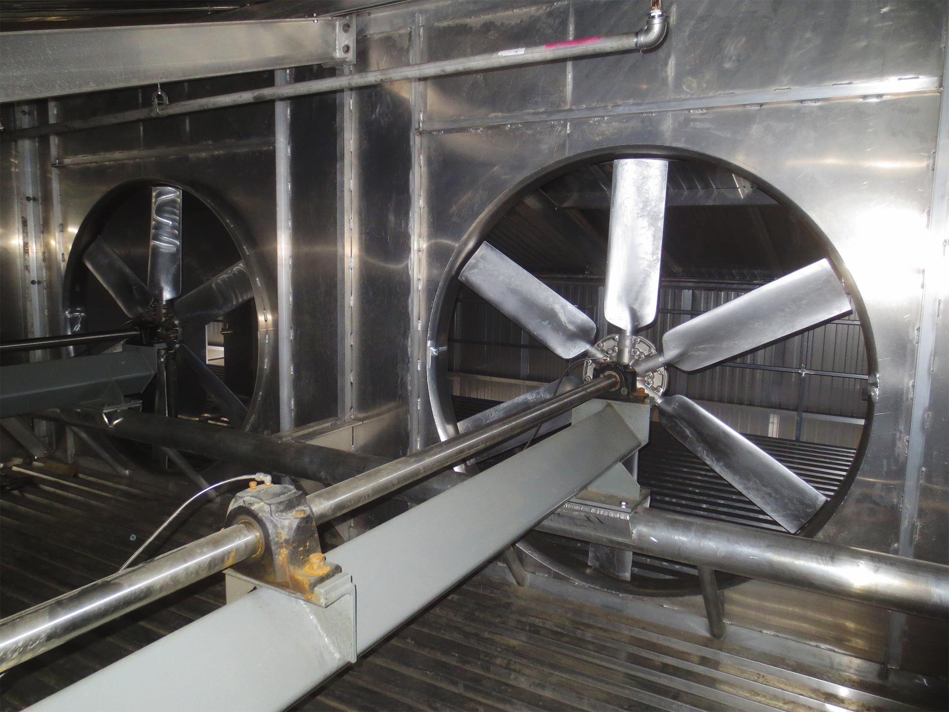
- Air Flow
Desired airflow (typically 1,000 to 1,200 fpm) can be achieved through a variety of fan configurations. The fans can be configured in a Single Air Pass configuration (2 fans on a single cross-shaft) or a Double Air Pass configuration (1 fan on a single cross-shaft).
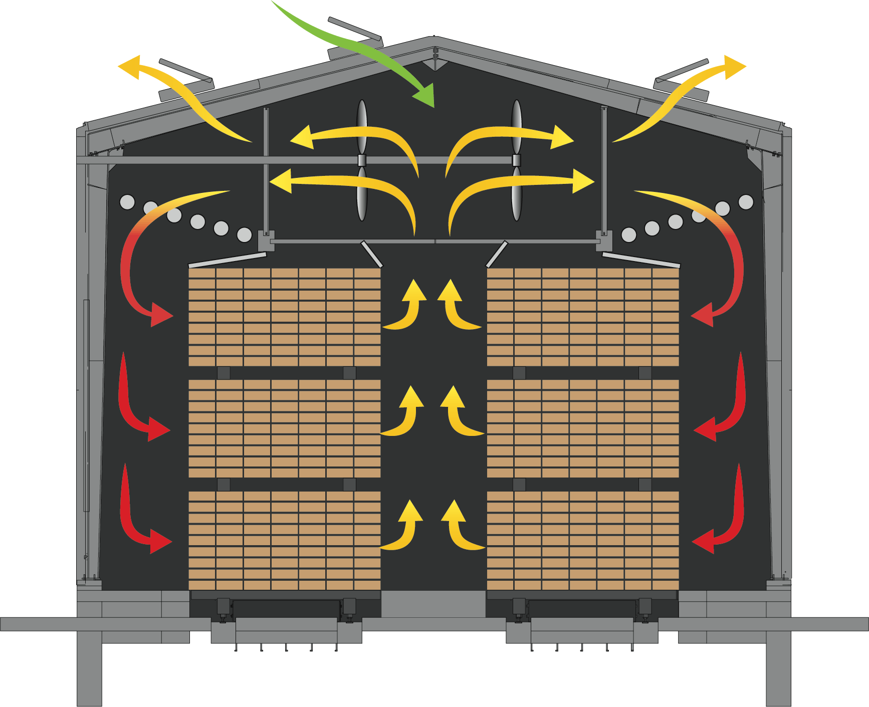
Single Air Pass
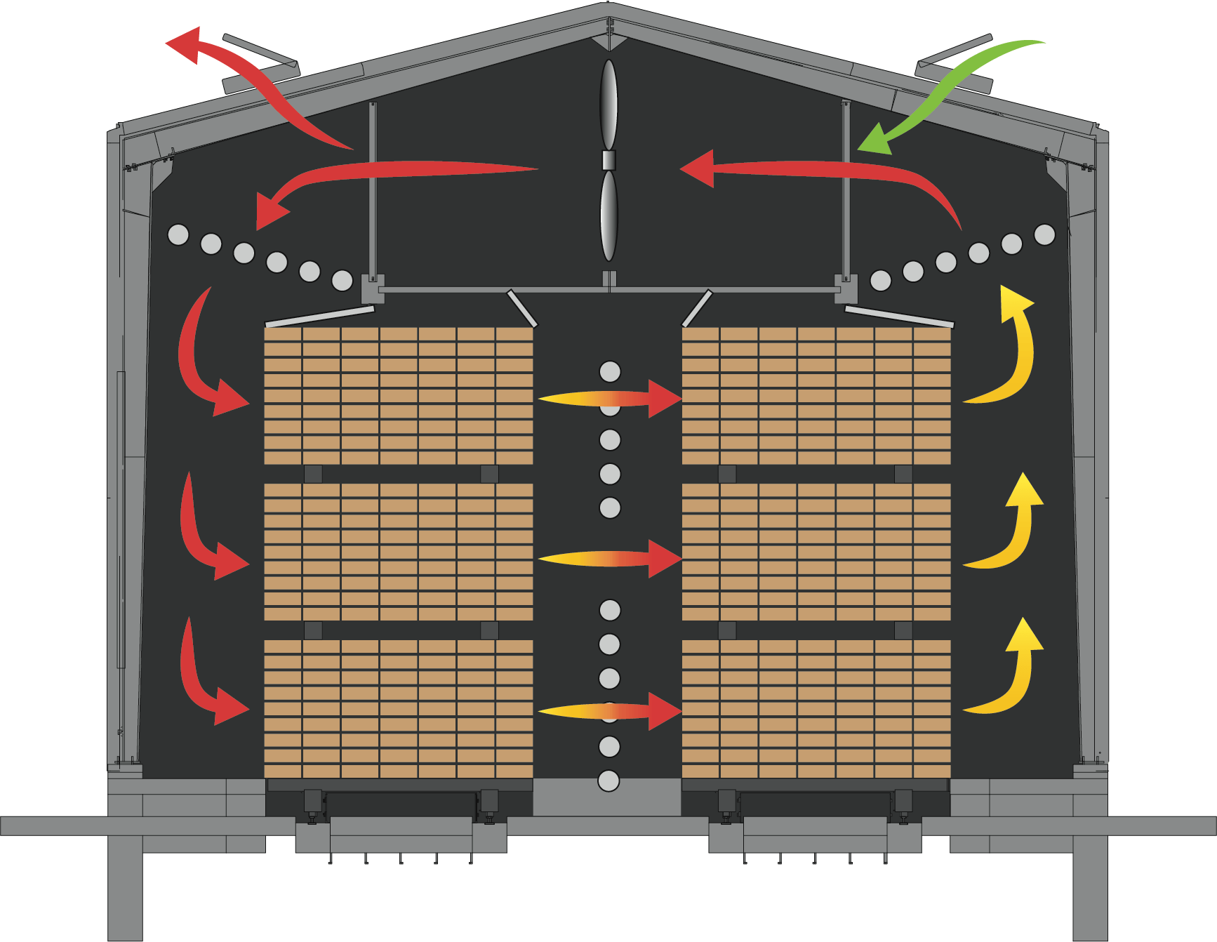
Double Air Pass
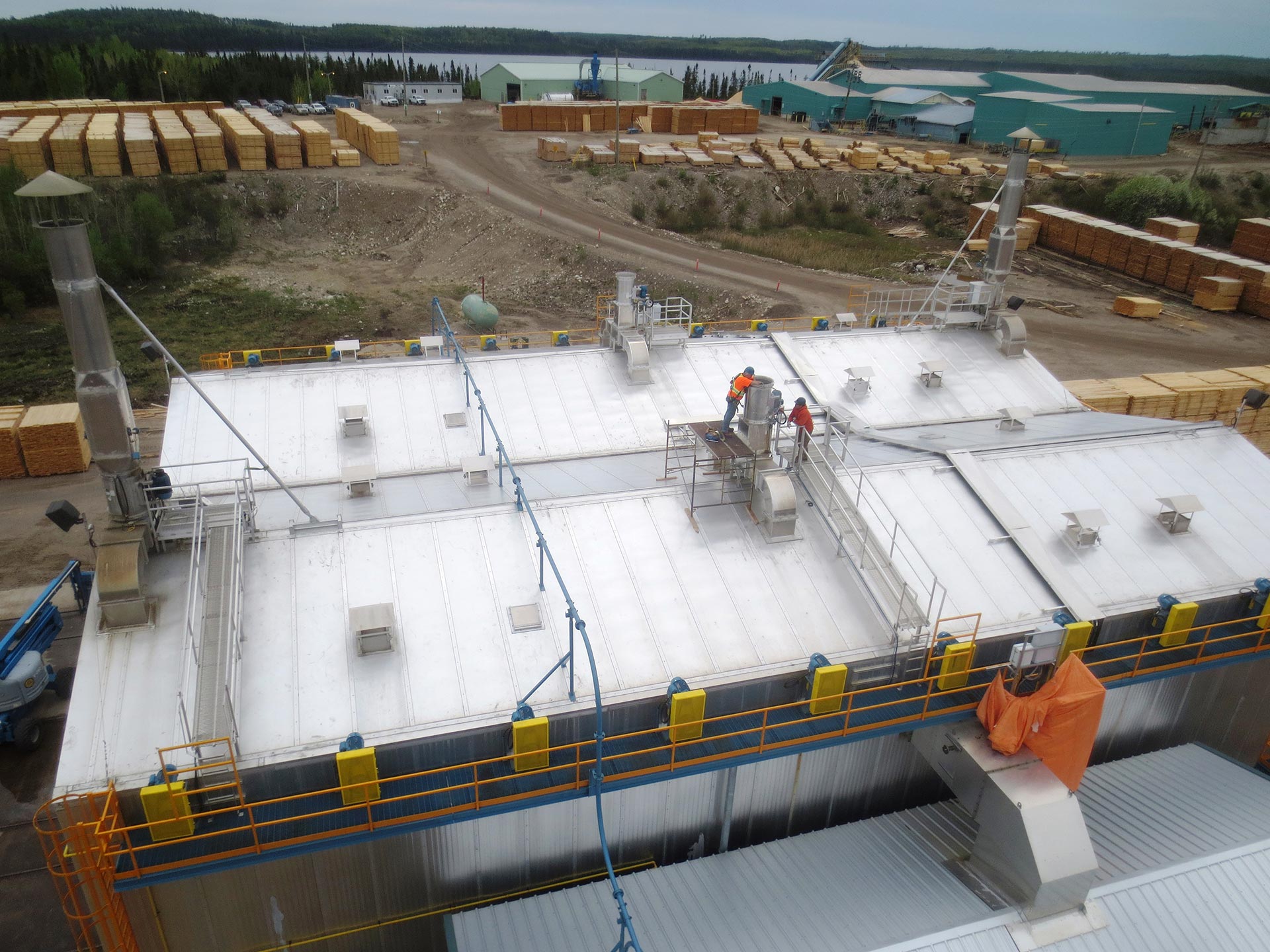
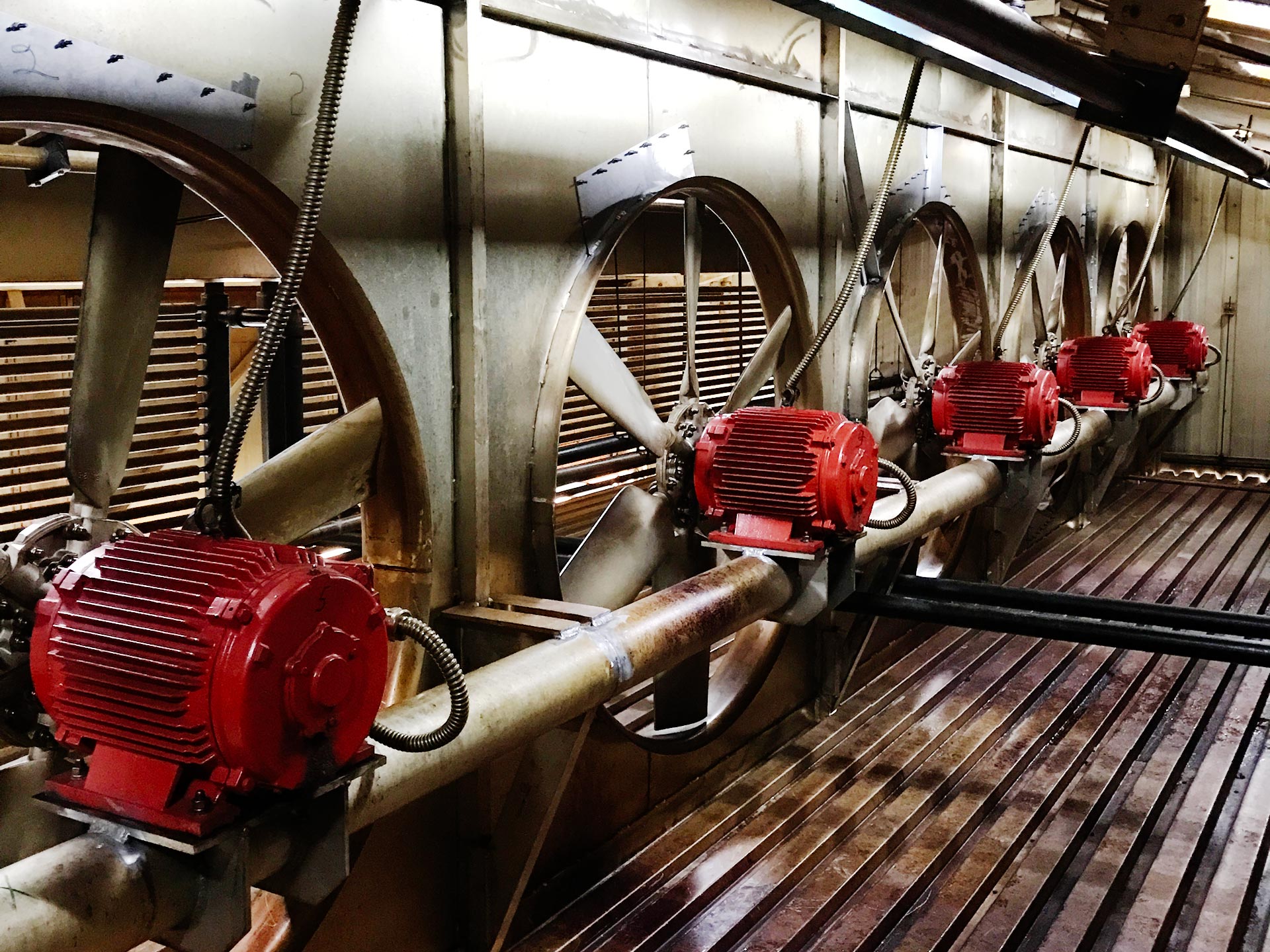
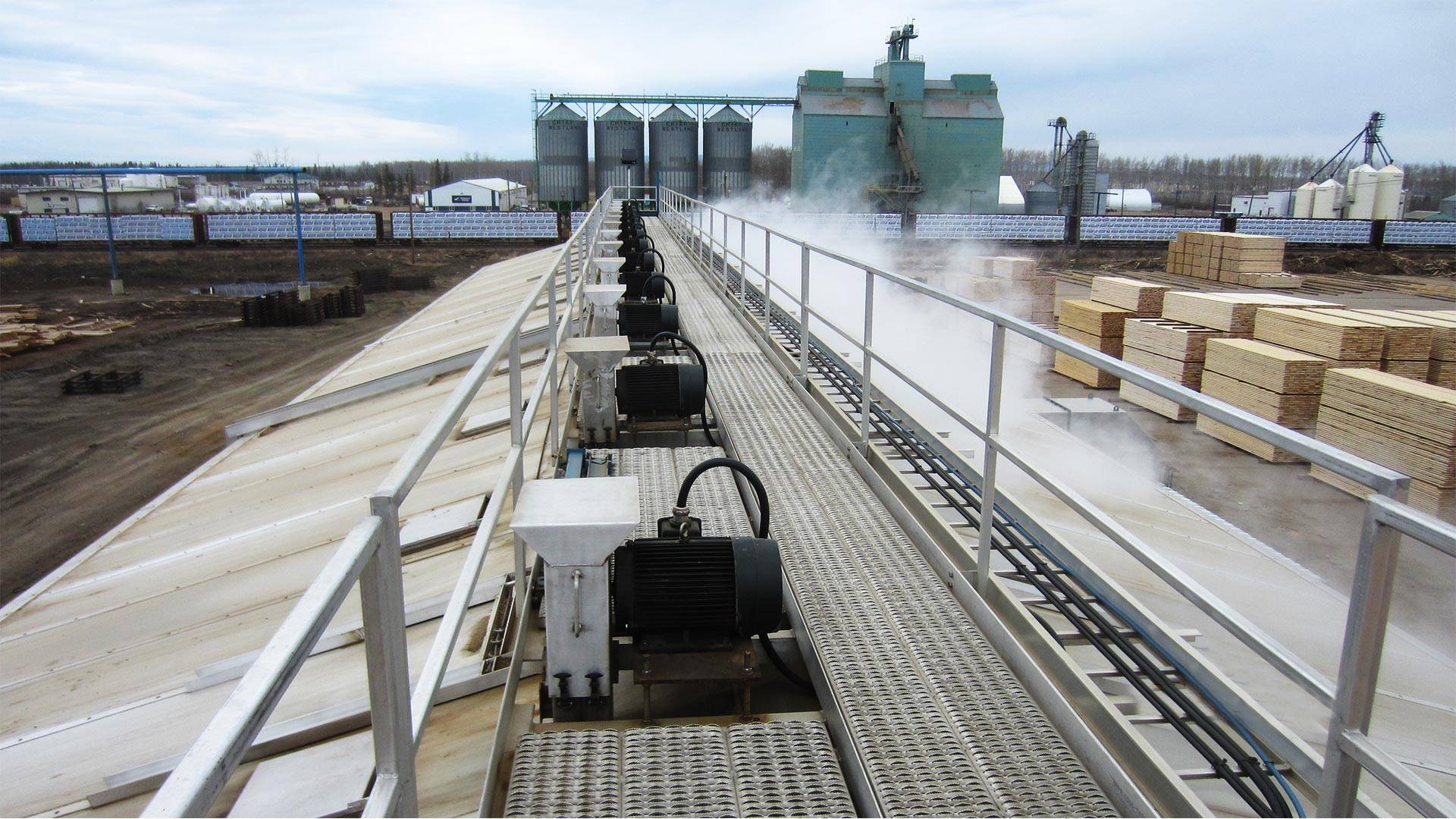
- Motor Mounts
The fans can be configured with walkway eave mounted motors, peak mounted motors, or in-kiln motors depending on the customer’s preference and the airflow requirements of the system.
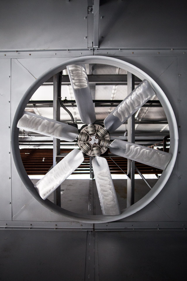
- Fans
The fans are industrial grade, all aluminum, fully reversible, adjustable pitch propeller blade fans. Wellons uses 72” 6-blade, 76” 8-blade, or 84” 12-blade Smithco fans to achieve its air flow performance.
The fan shaft bearings are fitted with convenient external lubrication fittings to facilitate preventative maintenance.
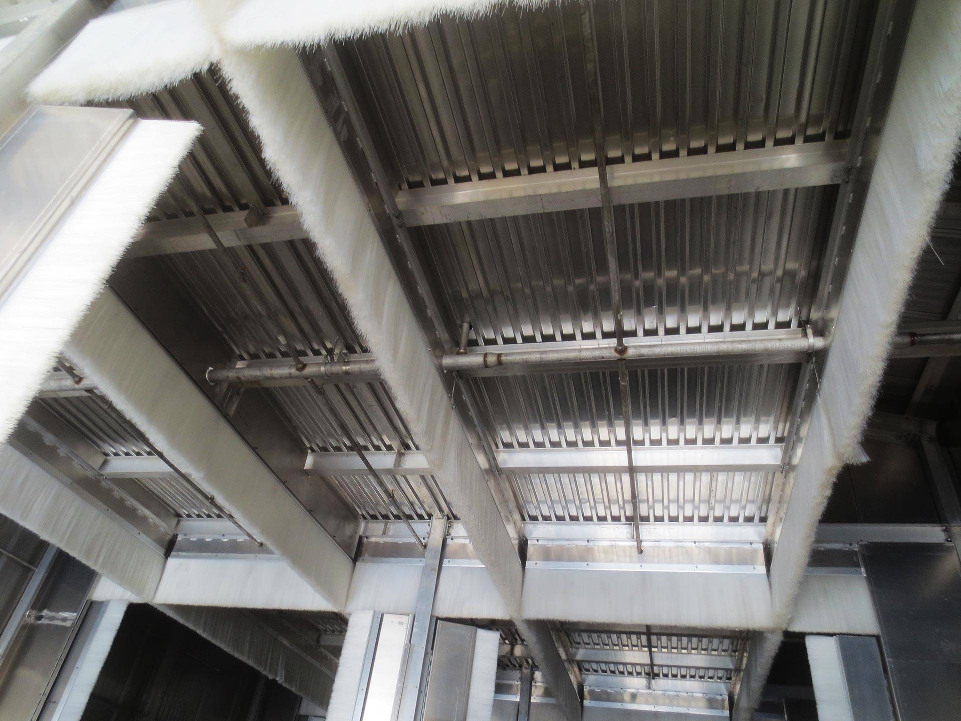
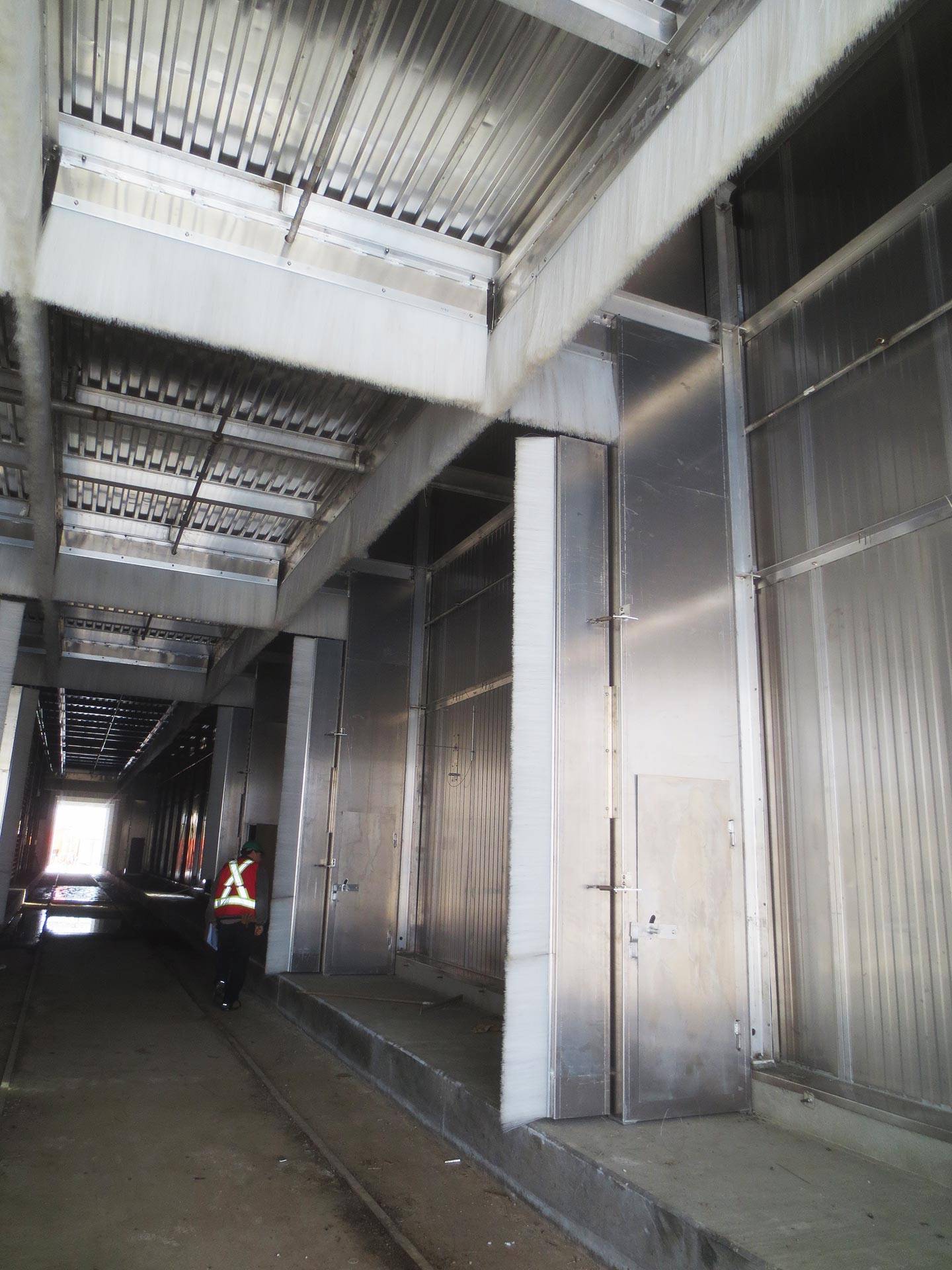
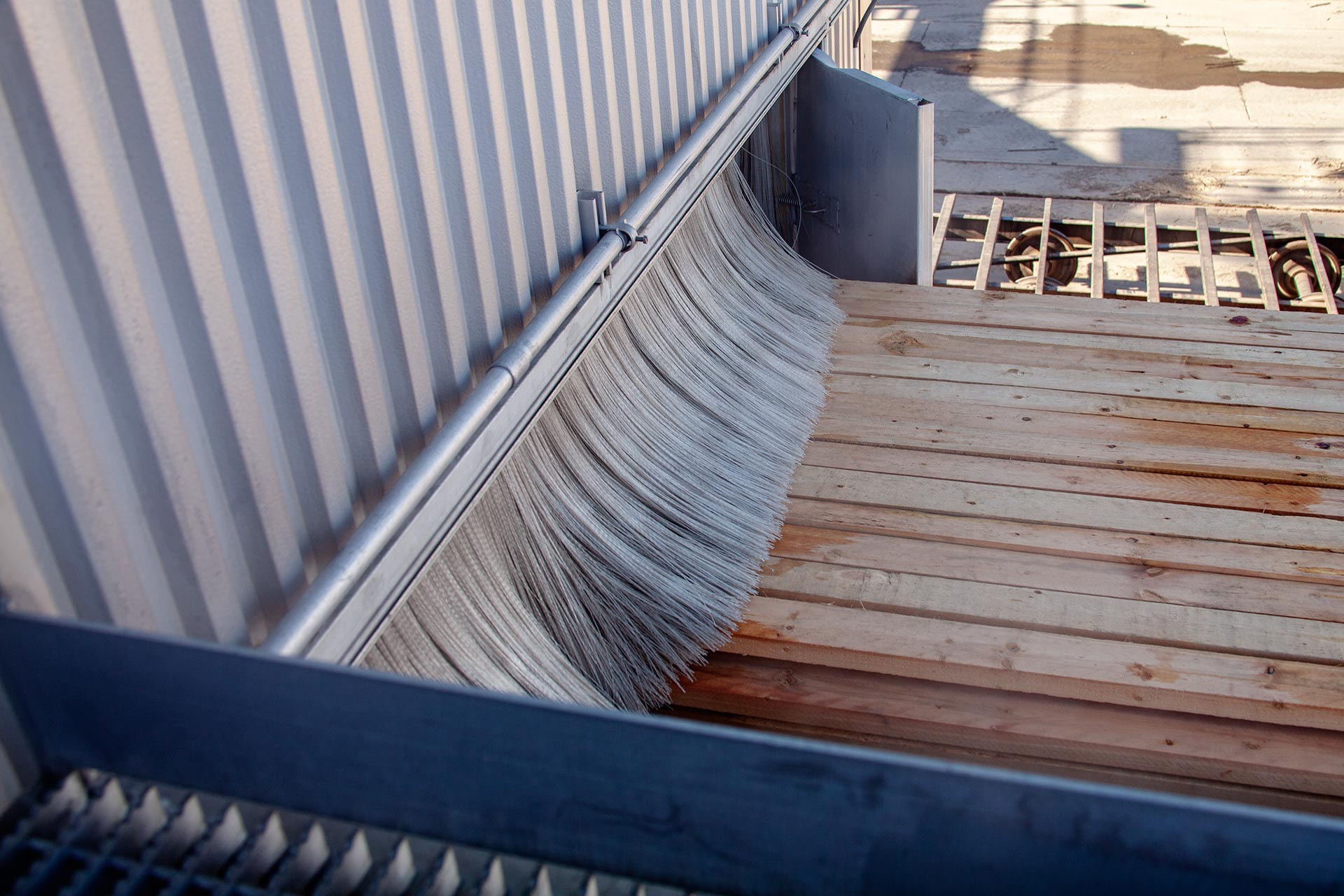
- Baffles
A variety of baffles are provided to keep airflow directed through the lumber and prevent air passage around the load. Ceiling, floor, and end-wall baffles are standard equipment.
The wall and ceiling baffles can be fitted with brush baffles to improve isolation of the chambers and provide longer life to the fixed baffles.
Continuous Drying Systems
Features & Options
Many of the proven design features of the Wellons track kiln design are incorporated into the Continuous Drying Systems to ensure superior performance and long operating life.
Wellons proprietary Winkiln control software has it roots in multi-zone design for optimal drying control. Winkiln is a non “black box” technology that uses off-the-shelf OPTO 22 or PLC I/O; or it can be configured using a PLC in a true HMI format. With the ability to control single zone direct fired systems, or twenty-four zone indirectly heated systems, Winkiln is user friendly and flexible.
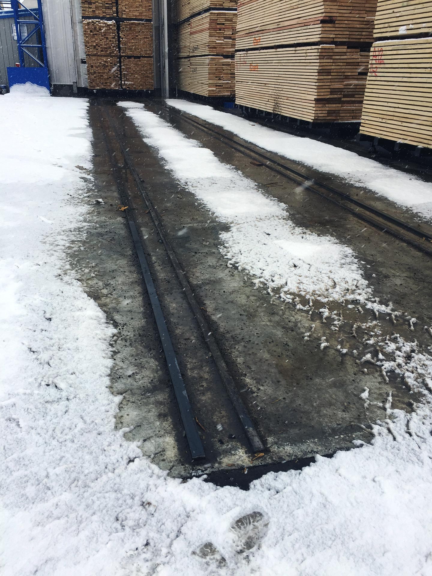
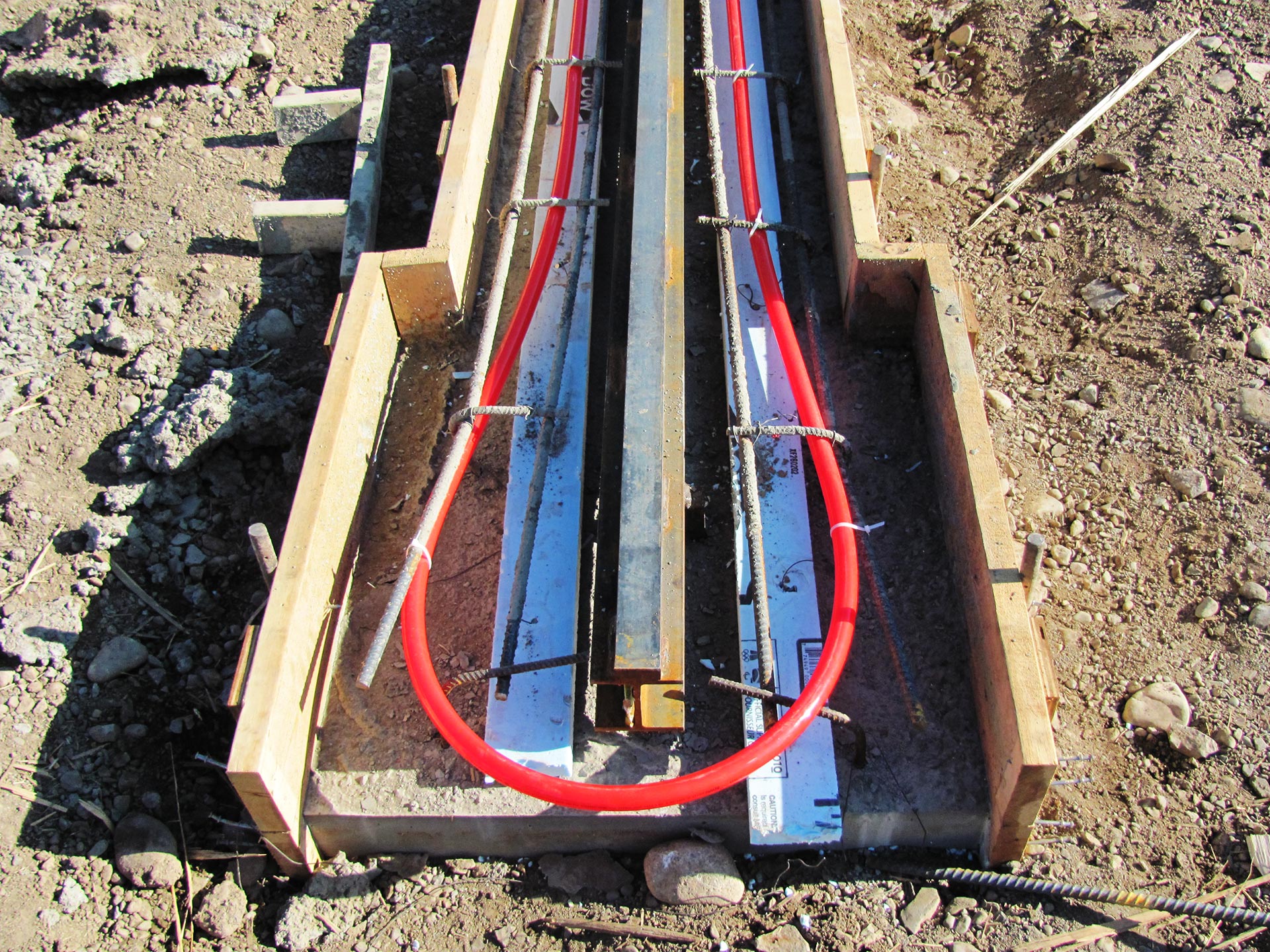
Wellons has experience providing rail heat in harsh winter conditions which can be an essential addition to a new drying system or as an upgrade to an existing kiln ensuring uninterrupted operations during inclement weather.
Rail Heat Sources
Regardless of your heating system for lumber drying, Wellons can provide rail heat with any of the following energy sources:
- Natural Gas – Gas fired glycol heater
- Propane – Propane fired glycol heater
- Thermal Oil – Thermal oil to glycol heat exchanger
- Steam – Steam to glycol heat exchanger
- Electric – If your current energy supply is not sufficient for rail heat, we can supply electric rail heat
Continuous Drying Systems
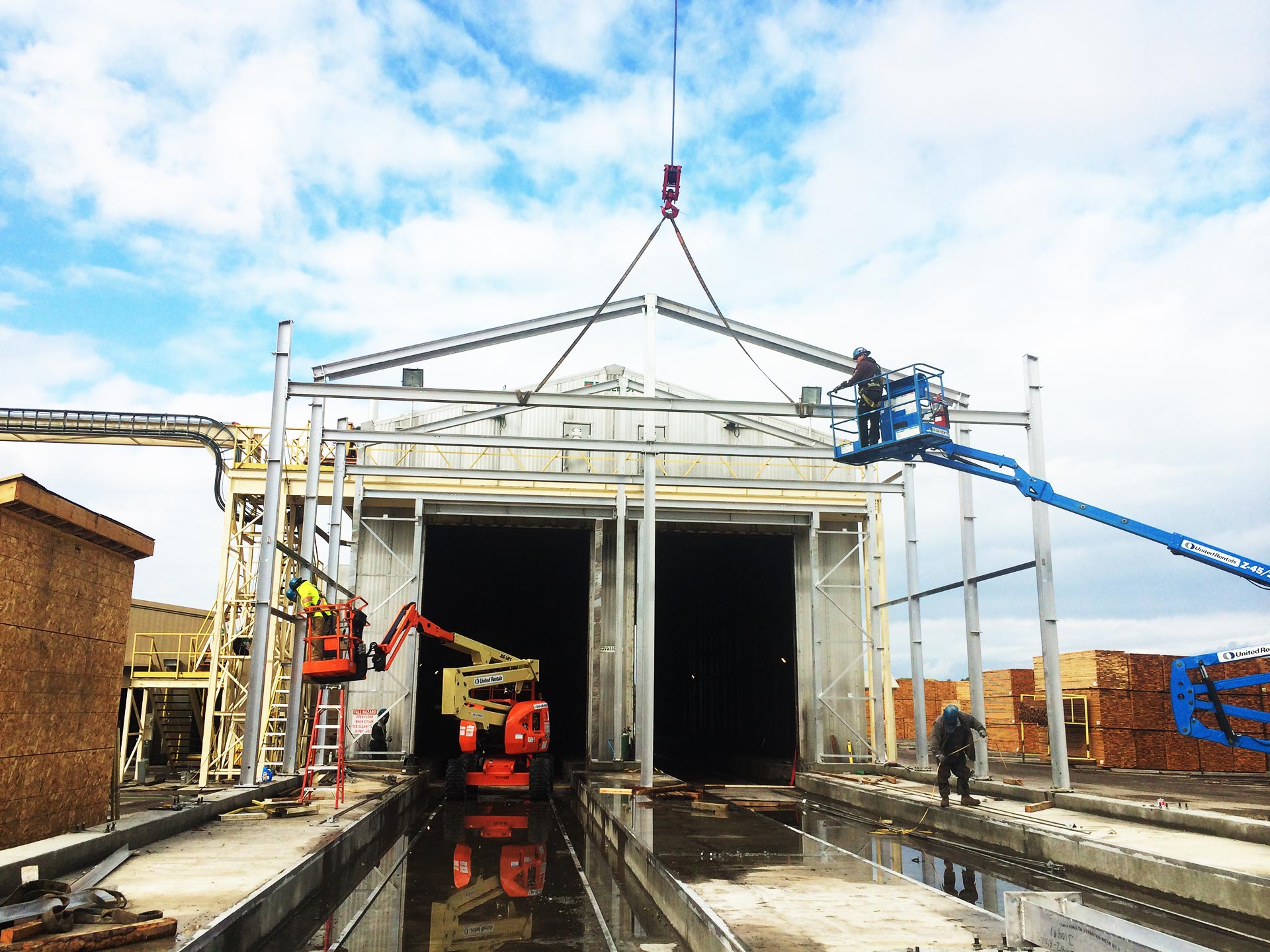
Retrofits of Existing Batch Kilns
The continuous drying approach can be applied to an existing double track batch kiln utilizing the existing energy source. Our extensive design capability and experience will ensure optimal operation of your retrofit Continuous Drying Systems.